Talk About Industry Articles
Control valves are one of the applications in home and industrial applications. We have talked about it in previous articles. In this article, in addition to an overview of its use, we want to introduce Control Valve Parts. Stay with us.

Parts of control valves:
Control valves are made of the following parts:
- Valve Disc
- Stem
- The body
- Packing
Read more here

What is Control Valve?
A control valve is a valve used to control fluid flow by varying the size of the flow passage as directed by a signal from a controller.This enables the direct control of flow rate and the consequential control of process quantities such as pressure, temperature, and liquid level.
In automatic control terminology, a control valve is termed a "final control element".
Bad fuel can cause key engine parts, such as the injection control unit, fuel pressure control valve, fuel oil pump or cylinder liners and piston rings to go from new to unusable in no time. Read more
The main purposes of control valves:
- Relieving the system from specific pressures
- Controlling the flow direction
- Increasing or decrease the flow
You can refer to the following links to read more about the different parts of control valves.
References:
https://www.linquip.com/blog/control-valve-parts/
In this article, we are going to examine the differences between globe valve and ball valve. We will first introduce each one separately. Then we examine their differences. If you want to know these differences, read this article to the end.
Ball Valve
A ball valve is a form of quarter-turn valve which uses a hollow, perforated and pivoting ball to control flow through it. It is open when the ball's hole is in line with the flow and closed when it is pivoted 90-degrees by the valve handle.The handle lies flat in alignment with the flow when open, and is perpendicular to it when closed, making for easy visual confirmation of the valve's status. The shut position 1/4 turn could be in either CW or CCW direction.
all valves are durable, performing well after many cycles, and reliable, closing securely even after long periods of disuse. These qualities make them an excellent choice for shutoff and control applications, where they are often preferred to gates and globe valves, but they lack their fine control in throttling applications. Read more here

Globe Valve vs Ball valve
the main difference of globe valve vs ball valve is the way they open and close the flow. A globe valve is used to control and throttle the flow while with a ball valve you can’t control the flow and the only thing you can do with the flow is to close it. With a globe valve you are able to regulate the flow whereas the ball valves are well-performed for the closing the flow without any pressure drops.
If you need to keep the flow closed for a long period of time, use a ball valve. A ball valve works more efficiently in high-pressure systems like fire hoses.

Globe Valve
A globe valve, different from ball valve, is a type of valve used for regulating flow in a pipeline, consisting of a movable plug or disc element and a stationary ring seat in a generally spherical body. High-head-loss valves, such as globe valves, are commonly used for control purposes. Significant losses occur with these types of valves, however, even when they are fully open. If the evaluation shows that a control valve is needed, choose the type that minimizes pressure drop across the valve. Read more

You can refer to the following sources to read more about globe valve and ball valve differences.
References:
https://www.linquip.com/blog/globe-valve-vs-ball-valve/
https://en.wikipedia.org/wiki/Globe_valve
https://www.energy.gov/sites/prod/files/2020/07/f76/CX-0265.pdf
DC generator is one of the most important parts in industry and electricity. In this article, we will first introduce the DC generator and then name and review the different parts of the DC generator.
In electricity generation, a generator is a device that converts motive power (mechanical energy) into electrical power for use in an external circuit. Sources of mechanical energy include steam turbines, gas turbines, water turbines, internal combustion engines, wind turbines, and even hand cranks. The first electromagnetic generator, the Faraday disk, was invented in 31 by British scientist Michael Faraday. Generators provide nearly all of the power for electric power grids. Read more
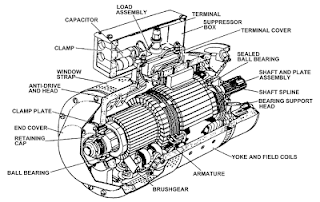
DC Generator Parts:
DC generators are generally made of
- the magnetic field systems
- shafts
- yoke
- brushes
- armature winding
- end housings
- pole shoes
- commutators
- bearings
Read more here.
In the following, we will examine each of these sections separately:
Yoke
If we divide the DC generator parts in two, Yoke is the outer cover that not only provides mechanical protection to the whole inner assembly and fixes them to the foundation of the machine, but also creates a path for the magnetic flow that the field winding produces.
Based on the size of the machines, yokes are of two kinds and materials; in large apparatuses, yokes are made up of cast or rolled steel while in smaller ones they are composed of cast iron.

To read more about the different parts of the DC generator, refer to the following sources.
The reverse conversion of electrical energy into mechanical energy is done by an electric motor, and motors and generators have many similarities. Many motors can be mechanically driven to generate electricity; frequently they make acceptable manual generators.

References:
https://www.linquip.com/blog/parts-of-dc-generator-explanation-working/
Industrial valves are not only used in industry but also in residential and commercial buildings. The main task of industrial valves is flow control. This article is an overview of industrial valves and their types and applications. Join us and read this article.
A valve is a device or natural object that regulates, directs or controls the flow of a fluid (gases, liquids, fluidized solids, or slurries) by opening, closing, or partially obstructing various passageways. Valves are technically fittings, but are usually discussed as a separate category. In an open valve, fluid flows in a direction from higher pressure to lower pressure. The word is derived from the Latin valva, the moving part of a door, in turn from volvere, to turn, roll. Click here

Valves are mechanical devices that control the flow and pressure within a system or process. They are essential components of a piping system that conveys liquids, gases, vapors, slurries, etc. Outside the home, industrial valves are built to control processes. Most utilities, from water to oil and gas, wouldn’t be able to function without heavy-duty, industrial-strength valves. So now that you know the importance of industrial valves, let’s get to know their different types, features, and usability. Follow this new blog in Linquip to find out more.
The general structure of industrial valves consists of the following parts:
- Body
- Valve Member
- Seat
- Stem
- Bonnet
- Actuator
- Valve Trim
- Stem Packing
Types of industrial valves
- Strainer Valve
- Electronic Expansion
- Control Valves
- PVC Foot Valves
- Ball Valves
- Plug Valves

Ball Valves
A ball valve is a form of quarter-turn valve which uses a hollow, perforated, and pivoting ball to control flow through it. It is open when the ball's hole is in line with the flow and closed when it is pivoted 90-degrees by the valve handle. The handle lies flat in alignment with the flow when open, and is perpendicular to it when closed, making for easy visual confirmation of the valve's status. The shut position 1/4 turn could be in either CW or CCW direction. Read more

To read more about industrial valves, you can refer to the sources mentioned at the end of the article.
References:
https://www.linquip.com/blog/industrial-valves/
https://en.wikipedia.org/wiki/Valve
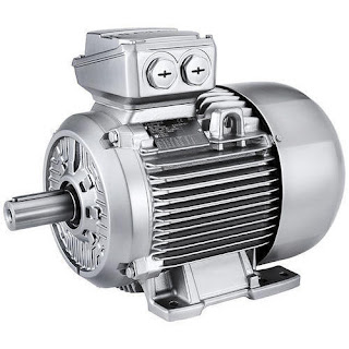
Surely you have heard the name of electric motors many times and you have information about it. In this article, we intend to define and study electric motors in more detail. We will also introduce the different types of electric motors and explain each one separately. Stay with us.
An electric motor is an electrical machine that converts electrical energy into mechanical energy. Most electric motors operate through the interaction between the motor's magnetic field and electric current in a wire winding to generate force in the form of torque applied on the motor's shaft. Electric motors can be powered by direct current (DC) sources, such as from batteries, motor vehicles or rectifiers, or by alternating current (AC) sources, such as a power grid, inverters or electrical generators. An electric generator is mechanically identical to an electric motor, but operates with a reversed flow of power, converting mechanical energy into electrical energy.
Using frequency converters means that the pumps can operate at optimum performance during any unloading conditions, resulting in higher total system efficiency and lower power consumption. When used as a direct drive force, electric motors also increase system efficiency compared with alternative systems.

Dramatic energy and cost savings can be achieved in motor systems by applying the best energy management practices and purchasing energy-efficiency equipment.
Types of Electric Motors
Electric motors are generally divided into two categories, AC and DC, and each of the thin categories includes other items.
- AC Motors
The AC motor is one of the types of electric motors that uses current with an alternating direction. These motors are not as easily speed-controlled as DC ones; however, with a bit of power penalty, one can use AC motors with variable frequency drives to have better speed control.
- DC Motors
In DC types of electric motors, DC electrical energy is turned into mechanical energy. DC motors can be whether self-excited or separately excited. However, the self-excited DC motors are probably more interesting if you can use them for your application. Read More Here
DC motors can also be classified based on whether they have brushed DC (BDC) or brushless DC (BLDC). Brushed DC motors are cheap and simple to design and manufacture; however, BLDC motors are complex and pricy. In general, small and insensitive applications such as appliances and car power windows and seats could use BDC motors, whereas applications such as HVAC and refrigeration, car electric motors, and other similar industrial systems would work with BLDC.

You can refer to the following sources to read more about electric motors types.
References:
https://www.linquip.com/blog/types-of-electric-motors/
- رویای بیت کوین Bitcoin Dream
- پرسش و پاسخ وردپرس
- سایت کیم کالا فروشگاه اینترنتی
- Lotus Water
- Psychology
- سایه وارونه
- داده پردازی نرم افکار
- اپیکیشن نت مانی net money
- مرکز تخصصی گچبری و قالبسازی آذین
- بیوگرافی
- ابوالفضل بابادی شوراب
- گروه هنری اولین اکشن سازان جوان
- اقیانوس طلایی
- .:: تنفّس صــــبح ::.
- شین نویسه
- خبر
- شهدای مدافع حرم
- پایکد
- نقاشی کشیدن
- درمان مو
- کبدچرب
- Sh.S
- نمونه سوالات استخدامی بانک تجارت (فروردین 1400)
- رسانه ارزهای دیجیتال و صرافی Coinex
- مرکز ماساژ در تهران
درباره این سایت